Cable Bus
Design Requirements
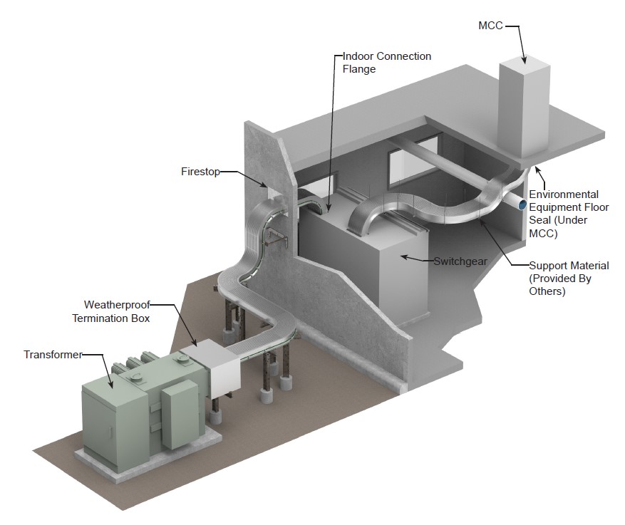
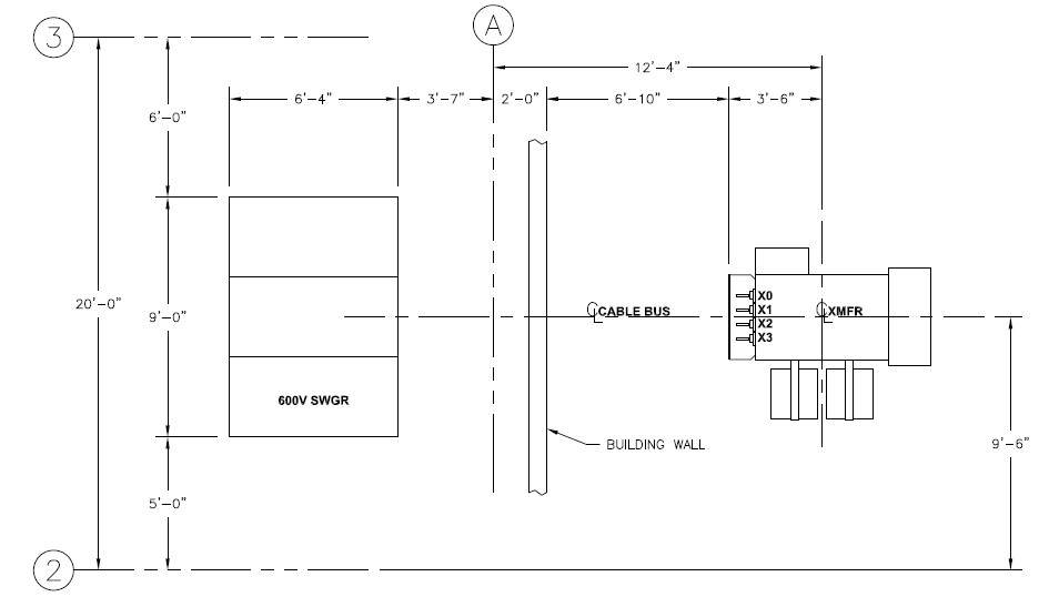
In order for MP Husky to proceed with the design of your cable bus system, the following drawings and information need to be submitted:
- Drawings & submissions, special requirements - engineer will provide any special client title block data electronically to MP Husky and MP Husky will add to the drawings.
- Equipment layouts, plan and elevation, tied to coordinate points, column lines, or site survey lines.
- Certified equipment drawings, showing location of termination points and available termination space, as follows:
Transformers
- Plan and elevation DWGs with centerlines
- Location of the bushing and throat flange relative to the XMFR base and centerlines.
- Transformer height from the base to top of cover mounted bushing.
- Horizontal distance from XMFR centerline to bushing centerline of cover mounted bushing.
- XMFR height from base to horizontal centerline of sidewall mounted bushing.
- Horizontal distance from XMFR centerline to bushing extension of sidewall mounted bushing.
- Bushing drilling pattern and hole spacing.
Switchgears
- Plan and elevation outline DWGs with centerlines.
- Side section DWGs showing cable termination space.
- Location of the bus bars relative to the switchgear base and centerlines.
- Bus bar drilling pattern and hole spacing.
- Location (e.g. bottom, top, or side) and size of the entry into the switchgear.
Buildings
- Plan and elevation outline DWGs with centerlines.
- Outer wall location, construction details, entry locations, and fire ratings.
- Dimensioned plan, elevation, and section views showing bus entry locations.
- Room elevation above grade.
- Equipment layouts referenced against coordinate points, column lines, or site survey grid.
- If cable bus entry is below, through the building floor, the following issues may apply:
- Time Rating of Fire Barriers.
- Floor construction details
- Method for fire barrier
- Mounting directly to the underside of the floor or a throat to which a barrier can be attached.
Typical Specifications
1.0 General
- A complete metal enclosed bus system shall be provided; including all necessary fittings, enclosure connectors, entrance fittings, insulated conductors, electrical connectors, terminating kits, and other accessories as required.
- The bus system shall be suitable for indoor or outdoor use with conductor spacing and ventilation maintained throughout the system.
- All elements of the bus enclosure shall be so designed as to eliminate any sharp edges or projections that may injure personal or conductor insulations.
- The bus system shall be Cable Bus, as manufactured by MP Husky.
2.0 Construction
- All load carrying members of the bus system shall be fabricated from extrusions of aluminum alloy 6063- T6. The maximum allowable stress used in designed shall be 10,000 PSI.
- 2.2 Bus enclosure fittings shall be in accordance with the minimum bending radius of the conductor requires a larger fitting radius.
- 2.3 The top and bottom enclosure sections shall be of flat design to provide mechanical strength and slotted for ventilation. The top cover shall be fastened to the enclosure with self tapping screws spaced approxi- ately 2 feet on centers and shall be removed for inspection. The bottom section shall be factory installed by welding.
- 2.4 Splice joints between sections of the bus enclosure shall be the high pressure splined bolted type of a design which avoids any structural weakness at the connection and does not exceed the electrical resistance specified under Section 3.4 of this specification.
- 2.5 Conductor support blocks shall be designed in segments to maintain the minimum of one conductor diameter in both the horizontal and vertical planes, as required for free air conductor rating. Horizontal runs will have blocks spaced
3.0 Electrical
- All current carrying conductors shall have insulation rated for 90°C operating temperature in accordance with ICEA publication #P-46-426 and interim STD #18#2 to ICEA publication #S-66-524 for the ampacity and voltage specified.
- 3.2 The conductors shall be phased and supported to maintain low impedance and assure the mechanical strength necessary to prevent cable movement or damage under short circuit currents up to 100,000 RMS symmetrical amps.
Conductors shall be of continuous length and be pulled in after the bus enclosure is in place. - 3.3 Electrical connectors shall be used only at the termination of conductor runs. All electrical connectors shall be provided by MP Husky.
- 3.4 The bus enclosure shall have a continuous current rating of not less than 1,000 amperes (50°C Rise) and the resistance across the enclosure section splice shall not exceed 50 microhms.
- 3.5 The bus enclosure shall be grounded at sufficient intervals for the purpose of preventing a potential above ground on the bus enclosure in the event of a fault.
- 3.6 The conductors shall be arranged in a phasing pattern which exhibits minimal inter-phase and intra-phase imbalance.
- 3.7 Conductor temperature rise and current balance data can be provided in support of Section 3.6 of this specification.
- 3.8 All transposing of cables must occur at termination points. Transposing of cables will not be done in the bus housing.


